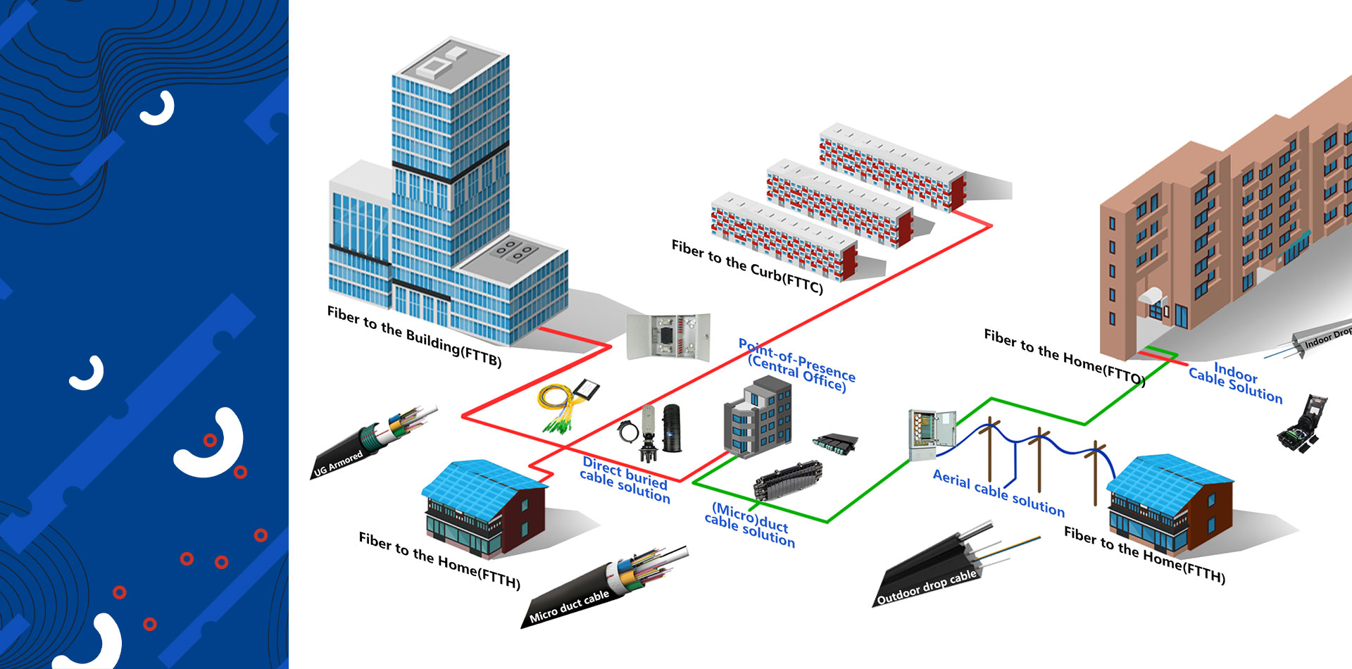
Aerial Fiber Optic Cable – Reliable Solutions for Overhead Optical Networks
Aerial fiber optic cables are designed specifically for overhead installations where optical fibers must be suspended between utility poles or transmission towers. These cables are widely used in telecommunications, broadband access networks, and FTTH (Fiber to the Home) projects, particularly in rural or suburban areas where underground deployment is costly or impractical.
Structure and Design
Aerial fiber cables are engineered to withstand environmental stress, including wind, temperature fluctuations, UV radiation, and mechanical tension. Depending on the installation requirements and environment, different cable types are used, such as:
Figure-8 Self-Supporting Cable
A widely used aerial cable with a built-in steel messenger wire, forming a “figure-8” shape. This design allows the cable to be suspended without additional support, making installation easier and more cost-effective. Common model: GYTC8S.
ADSS (All-Dielectric Self-Supporting) Cable
Constructed without any metallic components, ADSS cables are ideal for installation in high-voltage environments or areas with electromagnetic interference. They are lightweight, flexible, and have high tensile strength, suitable for long-span aerial installations.
ASU (Aerial Self-supporting Unit) Cable
A simple and economical aerial cable with parallel structure—fibers on one side, steel wire on the other. Its compact form is easy to deploy and maintain, especially in short-span FTTH drop applications.
Key Features
High Tensile Strength
Designed to endure long spans between poles without sagging or breakage.
UV and Weather Resistance
The outer jacket is typically made of UV-resistant polyethylene, protecting the fibers from sunlight and harsh weather.
Waterproofing & Rodent Protection
Filled with water-blocking gel or dry water-blocking yarns to prevent moisture ingress; armored options available for rodent resistance.
Cost-effective Deployment
Ideal for rapid network expansion without the need for trenching or underground duct systems.
Applications
Broadband expansion in rural and underserved areas
Power utility communication networks (ADSS)
Aerial drops in FTTH deployments
Emergency or temporary fiber network setups
Integration with pole-mounted equipment and distribution boxes
Technical Options
Fiber Count: Typically ranges from 2 to 144 cores, depending on network requirements
Cable Span Length: From short drops (30–80m) to long-distance spans (up to 800m+ for ADSS)
Standards: Complies with ITU-T G.652D/G.657A, IEC, Telcordia, and other international standards
Aerial fiber optic cables offer a robust, economical, and flexible solution for modern telecommunication networks. Whether for urban upgrades or rural fiber rollouts, their ability to deliver high-speed data over long distances with minimal infrastructure makes them an essential part of global broadband infrastructure.
Step-by-Step Installation Process
1. Site Survey and Planning
Inspect the route: Check terrain, existing poles, vegetation, and accessibility.
Confirm span lengths, pole conditions, and necessary hardware.
Mark pole positions and verify compliance with local regulations and utility standards.
2. Material and Tools Preparation
Required tools:
Cable rollers
Pulley blocks
Dynamometer (for tension measurement)
Cable grips
Aerial bucket truck or lifting device
Personal Protective Equipment (PPE)
Typical materials:
Aerial fiber optic cable (ADSS or Figure-8)
Pole clamps and brackets
Suspension clamps and dead-end grips
Tension hardware
Grounding kits (if needed)
3. Pole Hardware Installation
Install pole hardware such as suspension clamps at intermediate poles and dead-end grips at termination poles.
For Figure-8 cables, fix the steel messenger wire portion directly to the pole bracket.
For ADSS cables, install armor rods and tension clamps for extra protection in windy areas.
4. Cable Unwinding and Laying
Use a cable drum mounted on a rotating stand.
Guide the cable through pulley blocks or rollers on each pole.
Ensure cable does not twist, kink, or scrape against sharp objects.
5. Tensioning and Sag Adjustment
Use a dynamometer to apply the correct tension as per the cable’s span and design specs.
Avoid over-tensioning, which can damage the fibers.
Adjust sag according to ambient temperature and span length (refer to cable manufacturer’s tension-sag table).
6. Securing the Cable
Fix the cable at each pole using dead-end grips at ends and suspension clamps at mid-spans.
Ensure there is no lateral or vertical movement under wind load.
Leave slight slack for thermal expansion/contraction.
7. Grounding and Bonding (if required)
For metallic cables (like Figure-8 with steel messenger), properly ground the messenger wire at intervals to avoid lightning damage.
Use ground rods and bonding clamps.
8. Splicing and Termination
Route extra cable length into splice closure boxes near poles.
Perform fusion splicing in a clean environment using OTDR-tested splicing machines.
Properly seal the closures with water-blocking materials.
9. Testing and Inspection
Use OTDR (Optical Time Domain Reflectometer) and Power Meter/Light Source to test:
Insertion loss
Return loss
Fiber continuity
Ensure the cable route is free from sharp bends or excessive tension.
Document test results for future reference.
Safety and Best Practices
Always wear PPE and follow electrical safety procedures near power lines.
Avoid working during storms or high winds.
Use warning signs and barriers when working near roads or public areas.
Do not exceed the cable’s maximum pulling tension or minimum bending radius.
Tips for Successful Aerial Installation
Plan installation during stable weather conditions.
Use slack loops or expansion coils at intervals to handle temperature changes.
Keep fiber splicing joints elevated and weatherproofed.
Regularly inspect pole hardware and tension after installation.
Post time: Apr-11-2025

