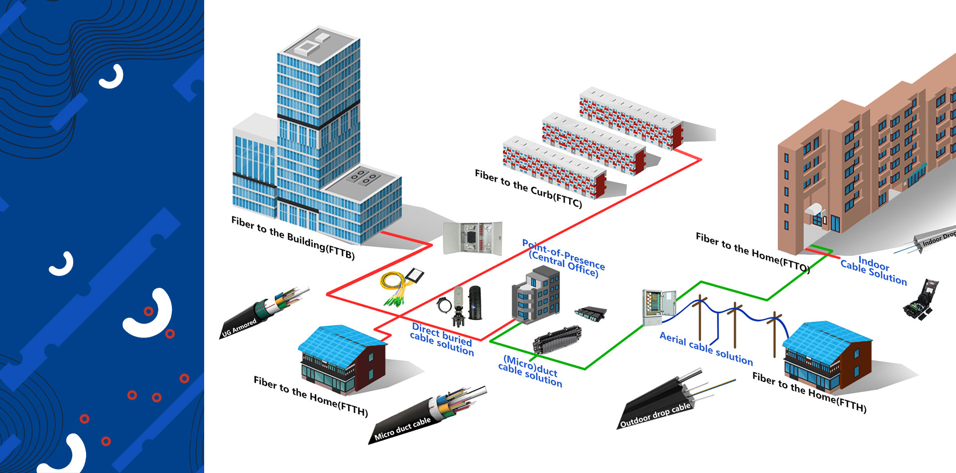
0.25mm/0.27mm G657A2 fiber refers to a specific type of single-mode optical fiber known for its exceptional bend-insensitivity, with the measurements indicating different layers of the fiber’s construction. This type of fiber is a popular choice for installations in tight spaces, such as in homes (Fiber to the Home – FTTH), data centers, and for specialized applications.
Key Characteristics of G657A2 Fiber
The G657A2 designation is an international standard (ITU-T G.657) that specifies the properties of bend-insensitive single-mode fibers. Key features include:
Exceptional Bend Performance: G657A2 fibers can be bent with a very small radius, as low as 7.5 millimeters, with minimal signal loss. This is a significant improvement over standard single-mode fibers (like G652D) which have a much larger bend radius. This flexibility allows for easier installation in corners and within compact enclosures without compromising signal integrity.
Compatibility: G657A2 fibers are fully compatible with the widely deployed G652D fibers, meaning they can be seamlessly spliced together in a network.
Wide Operating Wavelengths: These fibers are optimized to work across a broad range of wavelengths, from 1260 nm to 1625 nm, making them suitable for various communication applications.
Understanding the Fier Dimensions: 0.25mm and 0.27mm
The dimensions in your query, 0.25mm and 0.27mm, refer to the diameter of different layers of the fiber optic strand:
0.25mm (or 250µm): This is the standard diameter of the acrylate coating on the optical fiber. This coating is applied to the glass fiber (which itself has a cladding diameter of 125µm) to provide basic protection and handling properties. This is a very common specification for bare optical fibers.
0.27mm: This dimension typically refers to a buffered fiber. A buffer is an additional layer of protection applied over the coated fiber. While standard buffer sizes are often larger (e.g., 900µm), a 0.27mm diameter represents a very thin buffer or a specialized, ultra-thin cable jacket. This type of slim profile is particularly useful in applications where space is at an absolute premium, such as in high-density cables or for devices like drones that require lightweight and compact wiring.
In essence, you are looking at a highly flexible G657A2 optical fiber that has a standard 0.25mm coating, and in some configurations, may have a very thin additional protective layer bringing the total diameter to 0.27mm.
Why G.657A2 Fiber is Revolutionizing Drone Systems?
Lighter, Faster, and Farther
One of the most significant impacts of G.657.A2 fiber on drone technology is the substantial weight reduction it offers compared to traditional copper wiring. The fiber’s small diameter, often around 0.25mm to 0.27mm, and the use of lightweight materials in its cabling contribute to a lighter overall drone. This weight saving directly translates to increased flight endurance and the capacity to carry heavier and more sophisticated payloads, such as advanced sensors and larger batteries. Some industry reports indicate that using thinly coated G.657.A2 fiber can reduce cable cross-sectional area by as much as 60%.
G.657.A2 fiber provides the high-bandwidth and low-latency data transmission essential for modern drone operations. As a single-mode fiber, it can support data rates exceeding 10Gbps with minimal signal degradation over long distances. This capability is crucial for transmitting high-resolution 4K and 8K video feeds, real-time data from LiDAR and hyperspectral imaging sensors, and critical control commands with negligible delay.
G657A2 Mechanical Specification
|
Mode Field Diameter @ 1310 nm |
8.6 ± 0.4 um | ||
|
Mode Field Diameter @ 1550 nm |
9.8-10.8 um | ||
|
Cladding diameter |
125.0 ± 0.7um | ||
|
Core/cladding concentricity error |
0.5um | ||
|
Cladding non-circularity |
0.7 % | ||
|
Fiber curl radius |
≥4um | ||
| Primary coating material | UV curable acrylate | ||
| Primary coating Diameter | 245 ± 10um | ||
| Optical Characteristics | |||
|
Attenuation |
@ 1310nm |
0.34 dB/km |
|
| @ 1383nm± 3 nm |
0.31dB/km |
||
| @ 1550nm |
0.20dB/km |
||
| Dispersion | @ 1288 ~ 1339nm |
3.5 ps/nm×km |
|
| @ 1550nm |
18 ps/nm×km |
||
| Zero dispersion wavelength | 1300 – 1324 nm | ||
| Dispersion slope at zero dispersion wavelength | 0.092 ps/nm2×km | ||
| Cabled cut-off wavelength (lcc) | 1260 nm | ||
| Polarization mode dispersion link value | 0.2 ps/√km | ||
| Mechanical Characteristics | |||
| Proof stress level | ≥0.69 GPa | ||
| Effective group index of refraction Neff | 1.466(at 1310nm) | ||
| Effective group index of refraction Neff | 1.467 (at 1550nm) | ||
| 10turns radius 15mm 1550nm | 0.03dB | ||
| 10turns radius 15mm 1625nm | 0.1dB | ||
| 1turns radius 10mm 1550nm | 0.1dB | ||
| 1turns radius 10mm 1625nm | 0.2dB | ||
| 1turns radius 7.5mm 1550nm | 0.5dB | ||
| 1turns radius 7.5mm 1625nm | 1.0dB | ||
G657A1 Mechanical Specification for Comparation:
|
Characteristics |
Conditions |
Specified values |
Units |
|
|
Optical Characteristics |
||||
|
Attenuation |
1310nm |
≤0.35 |
[dB/km] |
|
|
1383nm(after H2-aging) |
≤0.35 |
[dB/km] |
||
|
1460nm |
≤0.25 |
[dB/km] |
||
|
1550nm |
≤0.21 |
[dB/km] |
||
|
1625nm |
≤0.23 |
[dB/km] |
||
|
Attenuation vs. Wavelength Max. α difference
|
1285-1330nm, in reference to 1310nm |
≤0.03 |
[dB/km] |
|
|
1525-1575nm, in reference to 1550nm |
≤0.02 |
[dB/km] |
||
|
Dispersion Coefficient |
1285-1340nm |
-3.5 to 3.5 |
[ps/(nm·km)] |
|
|
1550nm |
≤18 |
[ps/(nm·km)] |
||
|
1625nm |
≤22 |
[ps/(nm·km)] |
||
|
Zero Dispersion Wavelength(λ0) |
– |
1300-1324 |
[nm] |
|
|
Zero Dispersion Slope(S0) |
– |
≤0.092 |
[ps/(nm2·km)] |
|
|
Typical Value |
– |
0.086 |
[ps/(nm2·km)] |
|
|
PMD |
Maximum Individual Fibre |
– |
≤0.1 |
[ps/√km] |
|
Link Design Value(M=20,Q=0.01%) |
– |
≤0.06 |
[ps/√km] |
|
|
Typical Value |
– |
0.04 |
[ps/√km] |
|
|
Cable Cutoff Wavelength (λCC) |
– |
≤1260 |
[nm] |
|
|
Mode Field Diameter(MFD) |
1310nm |
8.4-9.2 |
[μm] |
|
|
1550nm |
9.3-10.3 |
[μm] |
||
|
Effective Group Index of Refraction(Neff ) |
1310nm |
1.466 |
– |
|
|
1550nm |
1.467 |
– |
||
|
Point Discontinuities |
1310nm |
≤0.05 |
[dB] |
|
|
1550nm |
≤0.05 |
[dB] |
||
|
Geometrical Characteristics |
||||
|
Cladding Diameter |
– |
125.0±0.7 |
[μm] |
|
|
Cladding Non-Circularity |
– |
≤0.7 |
[%] |
|
|
Coating Diameter |
– |
235-245 |
[μm] |
|
|
Coating-Cladding Concentricity Error |
– |
≤12.0 |
[μm] |
|
|
Coating Non-Circularity |
– |
≤6.0 |
[%] |
|
|
Core-Cladding Concentricity Error |
– |
≤0.5 |
[μm] |
|
|
Curl(radius) |
– |
≥4 |
[m] |
|
|
Delivery Length |
– |
Up to 50.4 |
[km/reel] |
|
|
Environmental Characteristics |
1310nm, 1550nm & 1625nm |
|||
|
Temperature Dependence Induced Attenuation |
-60℃ to +85℃ |
≤0.05 |
[dB/km] |
|
|
Temperature-Humidity Cycling Induced Attenuation |
-10°C to +85°C, 98% RH |
≤0.05 |
[dB/km] |
|
|
Watersoak Dependence Induced Attenuation |
23°C, for 30 days |
≤0.05 |
[dB/km] |
|
|
Damp Heat Dependence Induced Attenuation |
85°C and 85% RH, for 30 days |
≤0.05 |
[dB/km] |
|
|
Dry Heat Aging |
85℃, for 30 days |
≤0.05 |
[dB/km] |
|
|
G657A1 Mechanical Specification |
||||
|
Proof Test |
– |
≥9.0 |
[N] |
|
|
– |
≥1.0 |
[%] |
||
|
– |
≥100 |
[kpsi] |
||
|
Macro-bend Induced Loss |
10 Turns Around a Mandrel of 15 mm Radius |
1550nm |
≤0.25 |
[dB] |
|
10 Turns Around a Mandrel of 15 mm Radius |
1625nm |
≤1.0 |
[dB] |
|
|
1 Turn Around a Mandrel of 10 mm Radius |
1550nm |
≤0.75 |
[dB] |
|
|
1 Turn Around a Mandrel of 10 mm Radius |
1625nm |
≤1.5 |
[dB] |
|
|
Coating Strip Force |
typical average force |
1.5 |
[N] |
|
|
peak force |
1.3-8.9 |
[N] |
||
|
Dynamic Fatigue Parameter (nd) |
– |
≥20 |
– |
|
Post time: Jul-16-2025