
MPO Connector Types
An MPO connector is the core interface of an MPO cabling system. It enables multiple optical fibers to be connected simultaneously through a single ferrule, significantly increasing fiber density while reducing installation time. MPO connectors are available in different fiber counts, genders, polish types, and performance grades to support applications from 40G Ethernet to 800G AI data centers. If you wanna know more details about MPO Fiber Optic Solutions Pls check in our blogs.
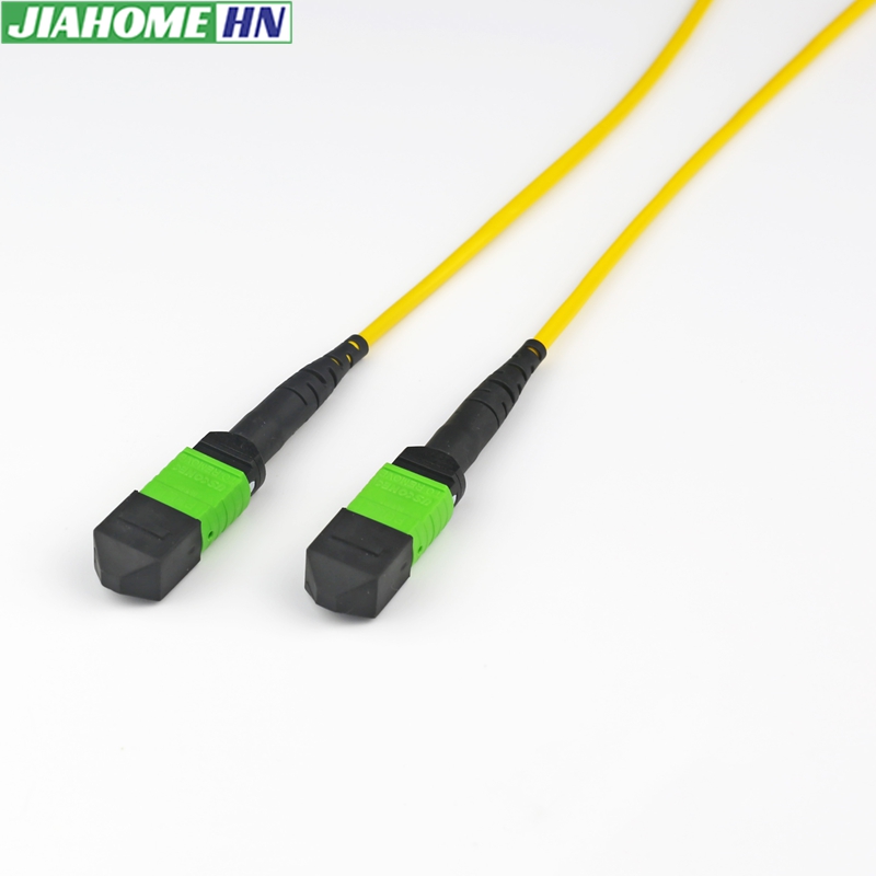
Although all MPO connectors appear similar externally, selecting the correct connector requires considering four key factors:
- Fiber count
- Connector gender (Male/Female)
- Fiber type (Singlemode or Multimode)
- Insertion loss grade
Choosing the wrong combination may result in polarity errors, excessive insertion loss, or complete link failure.
Anatomy of an MPO Connector
Every MPO connector consists of several precision-engineered components that ensure accurate fiber alignment and stable optical performance.
An MPO connector typically includes:
| Component | Function |
|---|---|
| Ferrule | Holds all optical fibers in precise positions |
| Guide Pins | Align two connectors accurately (Male connector only) |
| Guide Holes | Receive guide pins (Female connector only) |
| Housing | Protects internal components |
| Spring Mechanism | Maintains constant mating pressure |
| Strain Relief Boot | Protects cable from bending stress |
Unlike LC or SC connectors, where one ferrule contains a single fiber, an MPO ferrule accommodates multiple fibers in a single row (or multiple rows for higher fiber counts). The alignment tolerance is extremely small, making manufacturing precision critical to overall network performance.
MPO Connector Fiber Counts
The number of fibers inside an MPO connector determines its application, bandwidth capability, and compatibility with different Ethernet standards.
8-Fiber MPO
8-fiber MPO connectors are primarily used for:
- 40GBASE-SR4
- 400GBASE-SR4
- AI cluster networking
Advantages:
- No unused fibers
- Lower optical loss
- Higher efficiency
12-Fiber MPO
12-fiber MPO is the most widely deployed configuration in structured cabling.
Applications include:
- Enterprise data centers
- Campus backbone
- General-purpose structured cabling
Advantages:
- Highest compatibility
- Mature ecosystem
- Cost-effective
16-Fiber MPO
16-fiber MPO has become increasingly important with the adoption of 400G SR8 and emerging 800G applications.
Benefits include:
- Supports next-generation transceivers
- Better bandwidth utilization
- Future-ready infrastructure
24-Fiber MPO
24-fiber connectors are commonly used for:
- High-density backbone links
- Spine-leaf architecture
- Large hyperscale data centers
They reduce the number of cable assemblies required while simplifying cable routing.
Higher Fiber Counts
Available options also include:
- 32 Fiber
- 48 Fiber
- 72 Fiber
These are generally deployed in custom high-density environments such as AI supercomputing clusters and ultra-large cloud data centers.
Singlemode vs Multimode MPO
The choice between Singlemode and Multimode MPO depends primarily on transmission distance, network speed, and budget.
| Feature | Singlemode (OS2) | Multimode (OM3/OM4/OM5) |
|---|---|---|
| Fiber Color | Yellow | Aqua / Violet / Lime Green |
| Laser | LR/DR/FR | SR |
| Distance | Long | Short |
| Cost | Higher optics | Lower optics |
| Typical Use | Telecom, Metro, Long-distance | Data Centers |
Singlemode MPO
Recommended for:
- Metro networks
- Telecom backbone
- Long-distance transmission
- Outdoor deployment
Benefits:
- Lowest attenuation
- Virtually unlimited upgrade path
- Supports DWDM systems
Multimode MPO
Recommended for:
- Data centers
- Enterprise LAN
- Server rooms
- High-speed switch connections
Benefits:
- Lower transceiver cost
- Simplified deployment
- Excellent for short-distance high-bandwidth links
MPO Connector Gender
MPO connectors are classified as either Male or Female based on the presence or absence of guide pins.
This distinction is critical because two male connectors or two female connectors cannot be directly mated.
Male MPO
Characteristics:
- Contains two guide pins
- Provides alignment
- Often used on trunk cables
Female MPO
Characteristics:
- Contains guide holes only
- Receives guide pins
- Common on equipment connections
Standard Loss vs Elite Low Loss
Insertion loss is one of the most important performance indicators for MPO connectors. Lower insertion loss allows longer transmission distances and supports higher-speed applications.
Standard Loss
Typical insertion loss:
≤0.70 dB
Suitable for:
- Enterprise networks
- Standard structured cabling
- General-purpose installations
Low Loss
Typical insertion loss:
≤0.35 dB
Suitable for:
- 100G Ethernet
- 400G Ethernet
- Data centers
- High-density networks
Elite Low Loss
Typical insertion loss:
≤0.20 dB
Recommended for:
- AI data centers
- Hyperscale cloud facilities
- HPC clusters
- 800G Ethernet
As optical links become more complex with multiple cassette and connector interfaces, minimizing insertion loss becomes essential to maintain adequate link budgets and ensure reliable transmission.
MPO Connector Applications
Different connector configurations are optimized for different environments:
| Application | Recommended Connector |
|---|---|
| Enterprise LAN | 12F OM4 MPO |
| Cloud Data Center | 24F MPO |
| AI Computing Cluster | 16F Elite Low Loss MPO |
| Telecom Backbone | OS2 MPO |
| High-Density Patch Panel | Low Loss MPO |
| Spine-Leaf Network | 24F MPO Trunk |
MPO Polarity Explained
MPO polarity defines how optical fibers are mapped from one end of a cable to the other, ensuring that every transmitter (Tx) is connected to the correct receiver (Rx). Incorrect polarity is one of the most common causes of link failures in MPO networks.
In modern structured cabling, three standardized polarity methods are widely used:
- Method A (Type A)
- Method B (Type B)
- Method C (Type C)
Each method serves different deployment scenarios, and the correct choice depends on the transceiver type, cassette design, and overall network architecture.
Post time: Jul-29-2026